Related posts
Why Maglev and Screw Air Compressors Have Completely Different Sizing Logics
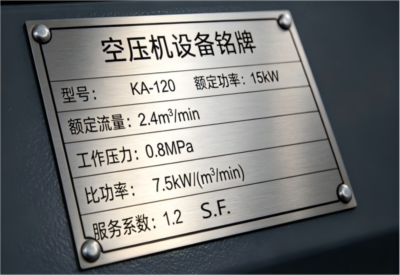
In the air compressor industry, miscalculating your equipment sizing can lead to two disasters: either a "big horse pulling a small cart" that burns through your energy budget, or constant system shutdowns that halt production.The root cause of this confusion usually comes down to one overlooked tec...

Data Center
In the digital era, Data Centers and Al Computing Centersrepresent the premier application arena for magnetic-bearingcompressors. Fundamentally, these facilities function as "heatsinks," where the energy consumption of their cooling systems(HVAC) typically accounts for over 90% of non-IT energy usag...

Commercial Buildings
In modern commercial real estate, balancing occupant comfort, long-term operational cost-effectiveness, and sustainability commitments is a universal challenge for premium offices, luxury hotels, and commercial complexes. Our Commercial HVAC Solutions are specifically engineered to address these dem...
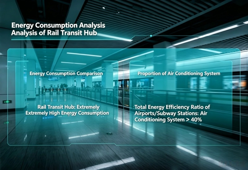
Rail Transit
Rail transit hubs like subway and railway stations are high-density public spaces operating round-the-clock under complex conditions. Our Rail Transit HVAC Solution focuses on addressing ventilation and cooling challenges in underground and expansive station environments. By integrating reliable, oi...
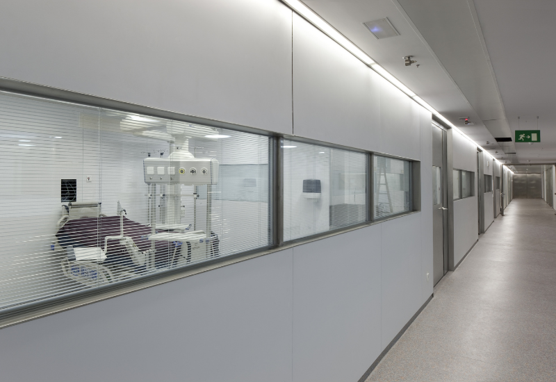
Public Facilities
Large public facilities, such as hospitals, exhibition centers, and stadiums, feature expansive spaces and diverse HVAC requirements depending on their function—hospitals demand strict air cleanliness and infection control, while venues and stadiums must manage fluctuating passenger loads in massive...

Cold Chain Logistics
Industry Pain Points & Needs
In the realm of warehousing and cold chain transportation, "constant temperature stability" and "energy efficiency" serve as key performance indicators. For large-scale cold storage facilities and long-distance cold chain operations—which requir...
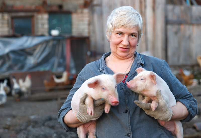
Livestock Breeding Environment Control
Modern livestock breeding, such as large-scale swine and poultry farms, relies on high-density, enclosed intensive production environments. Livestock are highly sensitive to indoor temperature, humidity, ammonia levels, and airflow, which directly impact animal health and yield. Our Livestock Breedi...
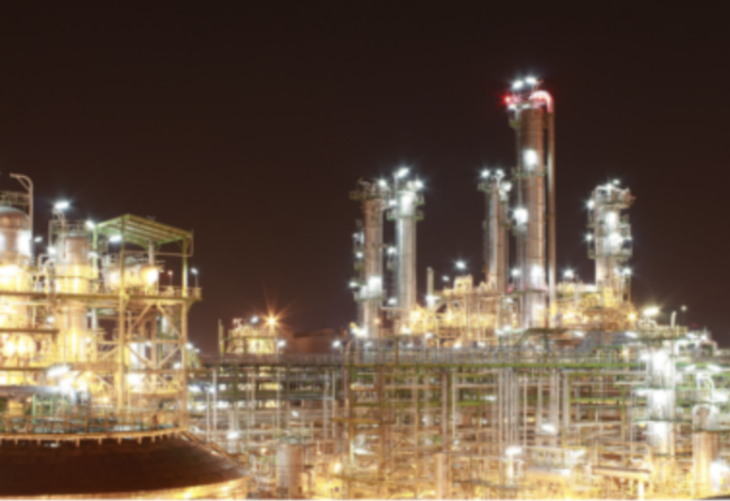
Metallurgy&Chemical Industry
The metallurgy and chemical industries, covering steel plants, chemical processors, and pharmaceutical facilities, involve complex processes characterized by extreme conditions such as high temperatures, high pressures, corrosive mediums, and hazardous environments. These factors demand strict safet...
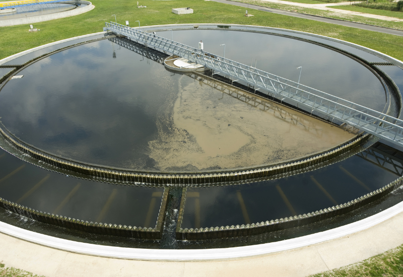
Water Treatment
Industry Pain Points & Needs
In the wastewater treatment industry, energy consumption constitutes a significant portion of total operating costs; specifically, the energy consumed by aeration systems typically accounts for 50% to 70% of a facility's total energy usage. With...
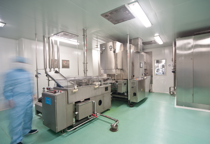
Food&Biopharma
The food processing and biopharma industries demand strict cleanliness and sterile standards, as any trace of oil contamination or cross-contamination directly threatens product safety and regulatory compliance. Our Food & Biopharma Solution focuses on meeting the rigorous requirements of proces...
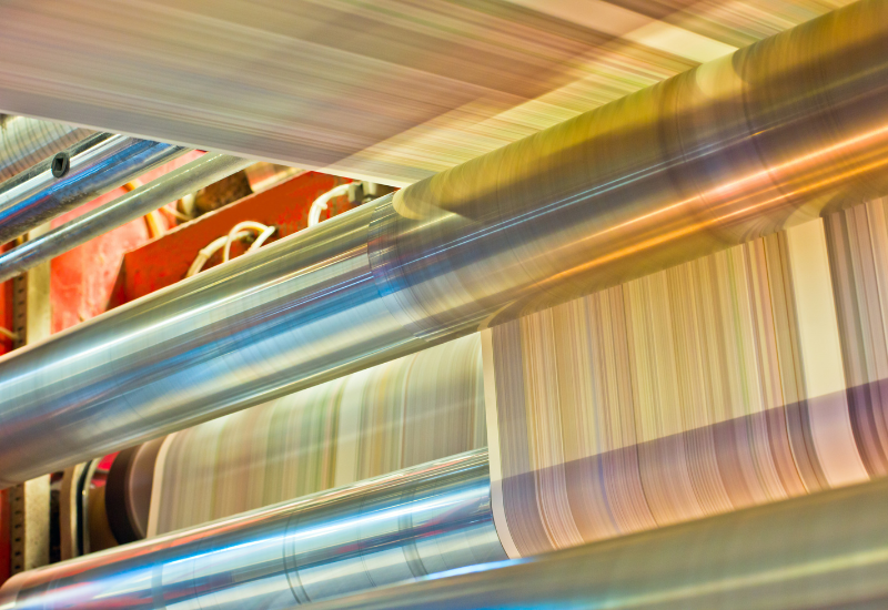
Textile & Paper Making
In the textile dyeing and papermaking industries, production processes rely heavily on high-quality compressed air, high-volume vacuum suction, and continuous operations. These two sectors are not only traditionally heavy consumers of water but also areas characterized by extremely high electricity ...
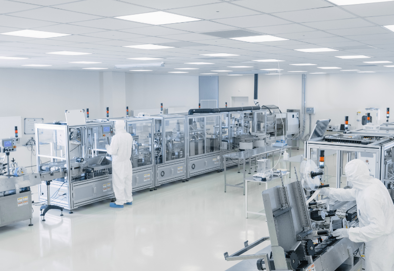
Electronics & Semiconductors
Electronics and semiconductor manufacturing, including wafer fabs, panel makers, and precision electronics facilities, requires ultra-clean environments with nearly zero tolerance for micro-vibrations, temperature fluctuations, or airborne contaminants. Our Electronics & Semiconductors Solution ...


Recent Comments