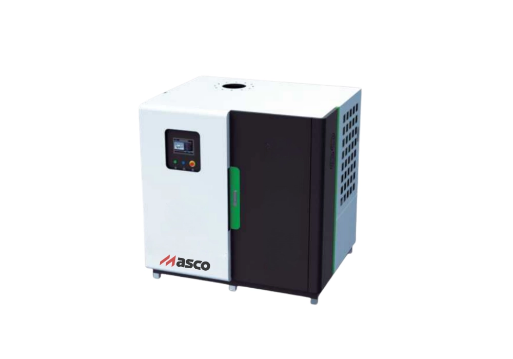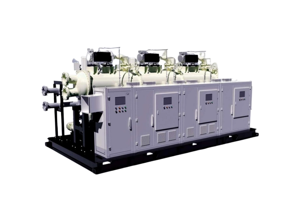

Maglev Water-cooled Centrifugal Chiller
Maximum energy efficiency, oil-free operation, COP>6,low total lifecycle cost
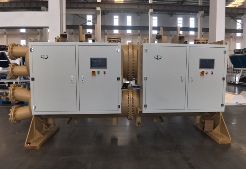
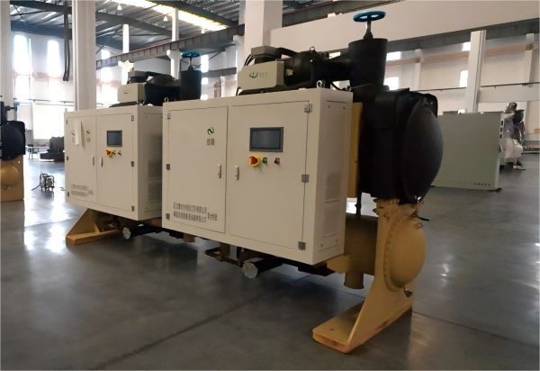
The Maglev Water-cooled Centrifugal Chiller represents the pinnacle of central air conditioning and process cooling technology. By utilizing industry-leading magnetic levitation oil-free technology, the system eliminates the complex lubrication oil systems found in traditional compressors. With ultra-high energy efficiency and exceptional stability, this product is widely used in large commercial complexes, data centers, hospitals, and high-end manufacturing, dedicated to creating a green and low-carbon temperature control environment for customers.
Product Advantages
- Ultra High Efficiency:COP>6, PLV far exceeds National Grade1 standard, 30%-50% annual electricity savings.
- Low Lcc: No oil system maintenance, fewer wearing parts, significantly reduce O&M costs.
- Low Starting Current: Soft-start technology with no impact on the grid, reduced investment in power distribution.
- Low Noise&Eco-friendly: Smooth operation without vibration, ultra-low noise. No expensive soundproofing required.
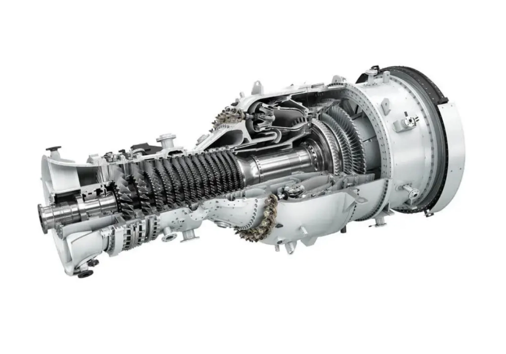
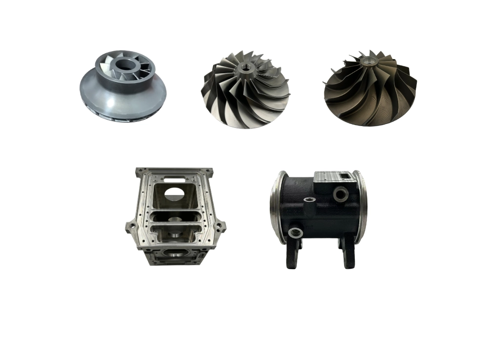
Core Technologies
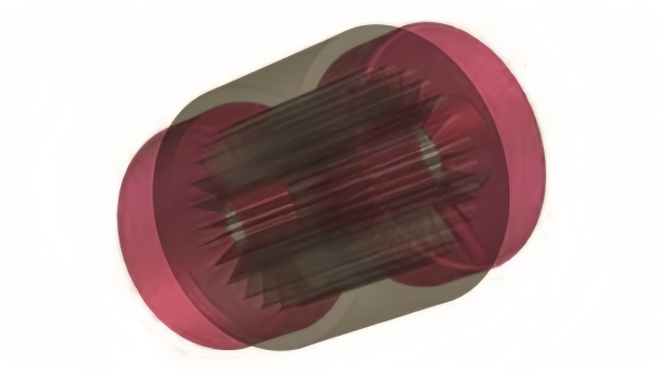
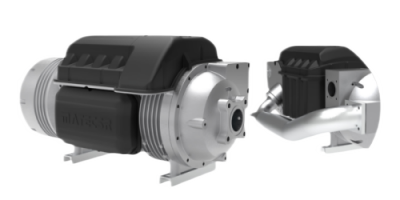
Features active magnetic bearing technology to eliminate mechanical friction losses, boosting system energy efficiency by over 30%.
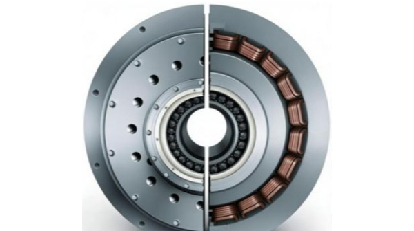
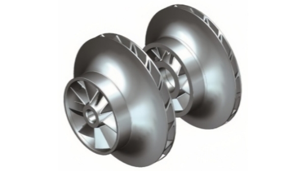
Employs a direct-drive configuration between the motor and compressor impeller—eliminating the need for speed-increasing gears—to achieve high power density, a compact footprint, design efficiency exceeding 98%, and stepless speed control.
Boasts an efficiency of over 83%, delivering a high single-stage compression ratio and a wide range of high-efficiency operation.
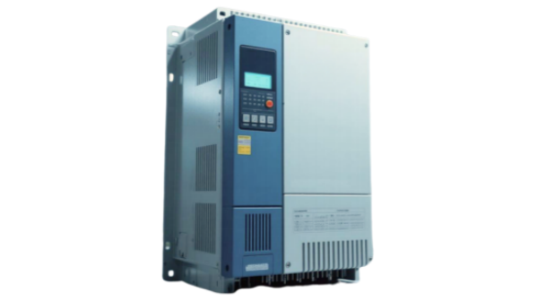
Precisely adjusts rotational speed in real-time based on load conditions, achieving exceptionally high efficiency under partial load conditions (IPLV).
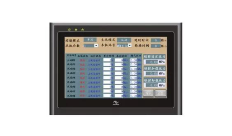
Incorporates power-loss protection and self-diagnostic functions to ensure the safe and reliable operation of the unit, even under extreme operating conditions.
Start Saving Energy
with
Frictionless
Technology
Working Principle
The unit utilizes magnetic bearings to support the compressor rotor, ensuring non-contact operation during rotation. In the refrigeration cycle, gaseous refrigerant is compressed by the high-efficiency maglev centrifugal compressor and then enters the condenser, where it liquifies through water cooling. It then passes through an expansion valve into the evaporator, vaporizing as it absorbs heat from the chilled water. Since the system is 100% oil-free, no oil film forms on the heat exchanger surfaces, significantly enhancing heat transfer efficiency.
Model Parameters
| Model | Unit | LY120 | LY200 | LY240 | LY400 |
| Cooling Capacity | RT | 120 | 200 | 240 | 400 |
| kW | 422 | 703 | 844 | 1407 | |
| Input Power | kW | 70 | 117 | 141 | 234 |
| COP | kW/kW | >6 | >6 | >6 | >6 |
| Starting Current | A | 2 | 2 | 2 | 2 |
| Power Supply | 380V-3P-50Hz | ||||
| Refrigerant | R134a | ||||
| Evaporator Flow Rate | m³/h | 73 | 121 | 145 | 242 |
| Condenser Flow Rate | m³/h | 85 | 141 | 170 | 283 |
| Unit Weight | kg | 3000 | 4000 | 4300 | 6000 |
Technical Parameters for Maglev Water-Cooled Units (Cooling/Heating)
| Model | Unit | LYS120L(L) | LYS200L(L) | LYS120ⅡL(L) | LYS200ⅡL(L) | LYS120ⅣL(L) | LYS200ⅣL(L) |
| Cooling Conditions | kW | 422 | 703 | 844 | 1407 | 1688 | 2814 |
| Ton | 120 | 200 | 240 | 400 | 480 | 800 | |
| Rated Power | kW | 67 | 112 | 134 | 223 | 264 | 440 |
| COP | W/W | 6.3 | 6.3 | 6.3 | 6.3 | 6.4 | 6.4 |
| Rated Current | A | 104 | 173 | 208 | 346 | 409 | 682 |
| Heating Conditions | kW | 443 | 735 | 883 | 1450 | 1770 | 2950 |
| Ton | 126 | 209 | 251 | 412 | 503 | 839 | |
| Rated Power | kW | 78 | 129 | 155 | 250 | 311 | 500 |
| COP | W/W | 5.7 | 5.7 | 5.7 | 5.8 | 5.7 | 5.9 |
| Rated Current | A | 120 | 200 | 240 | 388 | 481 | 775 |
| Max Operating Current | A | 155 | 238 | 310 | 476 | 620 | 952 |
| Power Supply Type | 380V/3N~50Hz | ||||||
| Load Control Range | 25%–100% Stepless Adjustment | ||||||
| Compressor | Type | Magnetic Bearing, Centrifugal Compression, High-speed PMSM | |||||
| Starting Current | <5A | ||||||
| Quantity | 1 | 1 | 2 | 2 | 4 | 4 | |
| Evaporator | Type | Shell and Tube Heat Exchanger (Flooded / Falling Film Type) | |||||
| Water Flow Rate (m³/h) | 73 | 121 | 146 | 243 | 292 | 485 | |
| Water Resistance (kPa) | 52 | 52 | 54 | 54 | 54 | 54 | |
| Condenser | Type | Shell and Tube Heat Exchanger | |||||
| Water Flow Rate (m³/h) | 44 | 73 | 87 | 146 | 175 | 291 | |
| Water Resistance (kPa) | 57 | 60 | 58 | 62 | 57 | 62 | |
| Refrigerant | Type | R134a | R134a | R134a | R134a | R134a | R134a |
| Charge Amount (kg) | 210 | 390 | 420 | 780 | 840 | 1400 | |
| Expansion Device | Electronic Expansion Valve | ||||||
| Dimensions | Length (mm) | 2600 | 4100 | 4200 | 4100 | 4900 | 6700 |
| Width (mm) | 1300 | 1250 | 1300 | 2500 | 2550 | 2700 | |
| Height (mm) | 1950 | 2250 | 1950 | 2250 | 1950 | 2550 | |
| Weight | Shipping (kg) | 2300 | 4300 | 4550 | 7100 | 9050 | 11700 |
| Operating (kg) | 2910 | 5090 | 5370 | 8280 | 10290 | 13500 | |
| Cooling Mode: Based on GB/T 18430.1. Chilled water inlet/outlet: 7/12°C; Cooling water inlet/outlet: 30/35°C. Heating Mode: Based on GB/T 19409. Hot water inlet/outlet: 38.6/45°C; Heat source water inlet/outlet: 15/6.3°C. For any non-standard requirements, please confirm with our professional technical staff. | |||||||
Unit Operating Specifications
| Category | Requirement / Specification |
| Voltage Fluctuation | ±10% (at constant rated frequency) |
| Voltage Sag | ≤15% within 2ms |
| Harmonics | Complies with GB/T 14594 (Power quality—Harmonics in public supply network) |
| Phase Imbalance | Voltage phase unbalance ≤ 2% |
| Frequency | ±5% (at constant rated voltage) |
| Ambient Temperature | 0°C to 35°C (Temperature within the installation space) |
| Relative Humidity | < 80%, non-condensing |
| Altitude | < 1000m (Higher altitudes may affect electrical insulation and conductivity, requiring special configuration) |
| Installation Guidelines | Environmental Protection: The unit must be installed in a well-ventilated indoor environment. It is strictly prohibited to store or operate the unit in areas exposed to rain, water droplets, or direct sunlight. Safety Distance: Do not install the unit near facilities where there is a risk of flammable gas leakage. Special Environments: For installations in coastal areas (high salinity), chemical plants, or environments with high concentrations of corrosive gases, a specialized unit design is required. Ventilation Requirement: The machine room must maintain adequate airflow to ensure the indoor ambient temperature does not exceed 35°C. |